A replacement ebike controller can have the correct-looking plugs and still be the wrong controller. The display powers up, but the motor stutters. The bike accelerates hard, then cuts out on the first real climb. Nothing looks broken, yet nothing works properly.
These faults come from treating the battery, controller and motor as three separate purchases. Electrically, they are one power system: the battery supplies energy, the controller meters it, the motor turns it into movement. Match the system and it is dependable. Match only the connectors and it is a gamble.
| THE SHORT ANSWERMatch voltage first — the controller must survive the battery’s full-charge voltage, not just its nominal label. Then set current to the LOWEST continuous ceiling in the chain: the battery BMS, the controller limit, and the motor’s sustainable thermal load, bounded by the wiring and connectors. Only after the limits are safe should you tune acceleration and ride feel.The counter-intuitive part: a bigger controller is not a safer controller. The system is only as strong as its weakest continuous link. |
What an Ebike Controller Actually Controls
The controller is often called the brain of the system, but a translator is the more useful image. It reads low-power instructions from the throttle, pedal sensor and brakes, then delivers high-power, precisely-timed current to the motor.
That translation happens thousands of times a second. The controller coordinates motor phase timing, requested battery current, throttle response, and protection signals — all at once. It also has to talk to the display, read the motor’s Hall sensors, and accept the brake and PAS inputs on the right pins.
So a correct voltage match is only the start. A controller that clears voltage but cannot read your motor’s sensors, or speak your display’s protocol, is still the wrong controller.
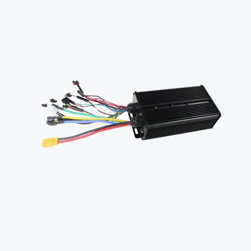
Every lead on a controller is a match to verify — motor phases, Hall sensors, throttle, PAS, brake cut-off, and the battery lead’s own current rating. [alt: high-power ebike controller with finned alloy case and full colour-coded harness including XT60 battery lead]
Match Voltage Before You Match Motor Wattage
The first buying check is battery voltage — and specifically the full-charge value, not the nominal label. A 52V pack reaches about 58.8V straight off the charger, and the controller must be rated to survive that peak, not merely the 52V on the sticker.
A lower-voltage battery can be just as incompatible. A 36V pack on a controller configured for 48V may read as empty to the low-voltage protection and refuse to run. Voltage mismatch is a hardware problem, not a settings problem.
This is worth stating plainly, because it is a common hope: reducing the current percentage in an app does not make an unsupported voltage safe. The controller still receives the full battery voltage the instant it is connected.
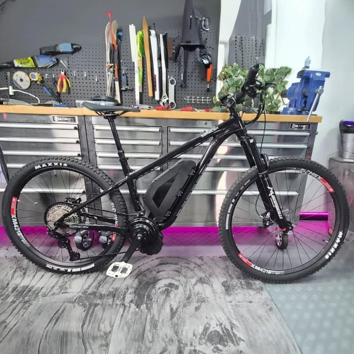
A finished build in the workshop — motor, battery and controller only behave as one system when their limits are set against each other, not chosen separately. [alt: completed e-bike conversion on a hardtail mountain bike with a triangle battery in the main frame]
Battery Current, Phase Current and Motor Watts Are Different
Controller listings often quote a single amp number without saying what it measures — and buyers then compare it directly with the wattage printed on a motor. That is where matching goes wrong.
| Figure | What it measures | Why it matters |
| Battery (DC) current | Current drawn from the battery | Loads the cells, BMS, connector and main power wiring — the number to match to the BMS |
| Phase current | Current circulating in the motor windings | Often higher than battery current at low speed; drives torque and motor heat |
| Motor watts (label) | A nominal rating, not a live measurement | A category, not a setting — don’t size a controller from it alone |
The quick estimate Voltage × Battery Current gives battery-side input, which is useful for comparing controller settings — but it is not wheel power, and it should not be read as the motor’s rating. A programmable 40A controller can suit several motor classes precisely because its battery current can be turned down.
Framework A: The Three-Ceiling Rule
A controller decision becomes simple once you identify three ceilings before choosing any current setting. The safe continuous current is the LOWEST of the three, with the connector and wiring as an extra boundary.
| Ceiling | Set it from | Not from |
| Battery ceiling | The pack’s continuous BMS and cell discharge capability | A brief peak figure |
| Controller ceiling | Its maximum battery current, and any app % limit converted to real amps | The headline amp number alone |
| Motor ceiling | Continuous thermal capacity — wheel size, gradient, rider load, cooling, duration | The wattage on the label |
A 40A BMS paired with a 60A controller is safe only if the controller is limited below 40A. And a 60A battery with a 60A controller still does not guarantee a small hub motor can take the load — the battery and controller stay comfortable while heat builds in the motor.
Here is the principle to keep: the BMS should be an emergency boundary, not a riding mode. If normal riding keeps tripping it, the controller setting is too aggressive or the battery is underspecified.
Framework B: Symptom, Cause, Ceiling
When a matched system misbehaves, the symptom usually points to the ceiling that was exceeded. Use this to diagnose before blaming a single part.
| Symptom | Likely cause | Ceiling / match at fault |
| Motor stutters or won’t self-learn | Hall/phase mismatch, or sensor protocol unsupported | Communication match, not current |
| Cuts out under load or on climbs | Controller draw exceeds BMS continuous rating | Battery ceiling |
| Motor gets very hot on long hills | Sustained current above the motor’s thermal duty | Motor ceiling |
| Powers up but reads empty / won’t run | Voltage config mismatch (e.g. 36V pack, 48V setting) | Voltage match |
| Strong launch then fade / shutdown | Aggressive setting trips BMS or overheats wiring | Controller setting vs battery/wiring |
| Connectors warm or melt | Current above connector/wire rating | Wiring boundary |
Why FOC Sine-Wave Control Changes Ride Quality
A field-oriented control (FOC) controller manages motor phase currents against rotor position, aiming for smooth magnetic control rather than coarse switching. The result is quieter running and a more linear, predictable power delivery.
That matters when ride quality counts as much as peak output. A commuter wants gentle engagement on a wet corner; a technical rider wants firmer response on a climb. Hall sensors normally report rotor position, while Hall-free operation and self-learning help a controller adapt to compatible motors.
What the Ride Power App Adds
A matched controller becomes a tunable one through the app. A Bluetooth-programmable ebike controller connects to the Ride Power app on iOS or Android, giving live readings alongside parameter controls refined over more than a decade of installation and tuning feedback. The value is not more power — it is the ability to set the limits deliberately and see what the system is actually doing.
Tune Current Before Acceleration
The safe tuning order is the reverse of what most riders try first. Acceleration strength is the fun setting, so it is tempting to start there — but current and protection should be set before personality.
- Save or export the original controller parameters.
- Confirm battery voltage and the controller’s supported input range.
- Set DC current to the battery’s continuous BMS limit and the motor’s sustainable load.
- Confirm low-voltage protection and the limit-current-voltage margin.
- Run self-learning where required; verify smooth, forward rotation.
- Begin with a moderate Accelerate Strength.
- Define PAS1–PAS5 for distinct situations.
- Test regen and any limit mode only once normal riding is stable.
Run the first powered test with the driven wheel off the ground and space to cut power safely. Protect the battery and motor first; tune the bike’s personality second — a smooth 70% that holds a long climb beats a dramatic 100% that overheats in minutes.
Regenerative Braking Is a System Feature
Regen is often sold as free range, but recovered energy is the smaller half of its value. On a compatible direct-drive hub, regenerative braking gives controlled deceleration and reduces mechanical brake wear.
Four parts must agree: the motor must generate through the wheel, the controller must support regen, the battery and BMS must accept charge current, and the brake input must trigger it. Near full charge the controller must cut regen current, because a full pack has nowhere to put the energy.
So the dependable benefit is braking control, not mileage. Any recovered range is a bonus that varies with terrain and battery state — geared hub motors, with their internal freewheel, usually cannot regen at all.
BMS Matching Starts with Continuous Current
Battery listings may show both continuous and peak discharge. For sustained riding, match the controller to the CONTINUOUS figure; peak is a short-duration allowance, not a riding budget.
When comparing matched ebike batteries for a conversion, check voltage, BMS continuous current, cell capability, connector and physical fit together — capacity in Ah or Wh answers range, not whether the pack can safely feed the controller. An app limit can pair a larger controller with a lower-current battery, but the maths must be explicit: a 60A controller set to 50% is intended to draw 30A, and that intent needs to sit under the BMS continuous rating.
Fully Potted Does Not Mean Maintenance-Free
Full resin potting protects the circuit board from moisture, vibration and road impact, and a thermally conductive compound can move heat from internal components to the case. It is a genuine durability advantage on an exposed conversion.
But potting does not remove every risk. Connectors, cable exits, damaged insulation and badly placed plugs stay vulnerable, and the case still needs a thermal path to shed heat. Keep connectors out of direct tyre spray, avoid low cable loops that collect water, and never wrap the case in insulating material.
UK Limit Modes Need Careful Legal Language
The Ride Power system offers three limited modes and an unlimited mode. Limited 1 applies a 250W / 25km/h setting to throttle and pedal assist; stricter modes disable the throttle or reduce it to walk-assist speed.
These configure behaviour — but a button does not certify a vehicle as road legal. Current UK guidance assesses the complete cycle, including continuous rated power and every accessible mode. The accurate claim is that Limit Mode can set lower power and speed behaviour; the owner must still confirm the whole vehicle complies for where it is ridden.
Buying and Installation Checklist
Confirm each of these before ordering, and again before the first ride.
- Battery nominal and full-charge voltage
- BMS continuous discharge current (not peak alone)
- Controller battery current and, where given, phase current
- Motor type, winding, Hall sensors and sustainable thermal load
- Display protocol and supported voltage
- Throttle, PAS, brake, light and alarm pinouts
- Battery connector polarity, wire gauge and current rating
- Controller case size, mounting position and heat path
- Self-learning / Hall-free support for the intended motor
- Regen capability across motor, controller, battery and BMS
- Bluetooth module and app compatibility
- Waterproof connector placement and cable strain relief
Frequently Asked Questions
What amp controller do I need for a 1000W ebike motor?
There is no universal number. At 48V, 1000W ÷ 48V is about 20.8A of idealised battery-side input, but acceleration peaks, efficiency and thermal limits change the real requirement. Size from the three ceilings, not the wattage alone.
Can I use a 60A controller with a 40A BMS?
Only if the controller is limited below the battery’s verified 40A continuous rating, with allowance for how peak and phase current behave. At an unrestricted 60A setting it will overrun the BMS.
Can the app make a large controller safe for a smaller motor?
The app can reduce battery current and soften acceleration, which helps — but it cannot change the controller’s voltage rating, connector compatibility or the motor’s thermal limit. Settings assist a good match; they cannot rescue a wrong one.
Does a higher-amp controller make an ebike faster?
More current mainly increases torque and acceleration, not unloaded top speed. Speed depends on battery voltage, motor winding, wheel size and controller field settings.
Does self-learning work with every ebike motor?
It is designed to identify phase and Hall relationships for many brushless hub motors. It does not guarantee compatibility with proprietary mid-drive systems or unusual sensor protocols.
Does regenerative braking work with a geared hub motor?
Usually not, because an internal freewheel lets the wheel spin without driving the motor backward. Direct-drive hub motors are far better suited to regen.
Is a fully potted controller waterproof?
Potting strongly protects the internal board against moisture and vibration, but it does not make connectors or damaged wiring submersible, and it does not remove the need for a thermal path.
Can Limit Mode make a high-power kit UK road legal?
Limit Mode can set lower output and assistance speed, but legality depends on the complete vehicle and all accessible modes. Check current official requirements for where the bike will be used.
Match the Limits Before You Tune the Ride
A controller should never be chosen in isolation. Start with battery voltage, BMS continuous current and the motor’s real thermal duty, then confirm communication, Hall, phase, brake, PAS and display compatibility before any performance setting.
The most useful controller is not the one with the biggest first-launch number. It is the one that stays below the battery’s reliable current, keeps the motor within its thermal duty, and communicates cleanly with the rest of the system. That is the difference between assembling powerful parts and engineering a dependable ebike.